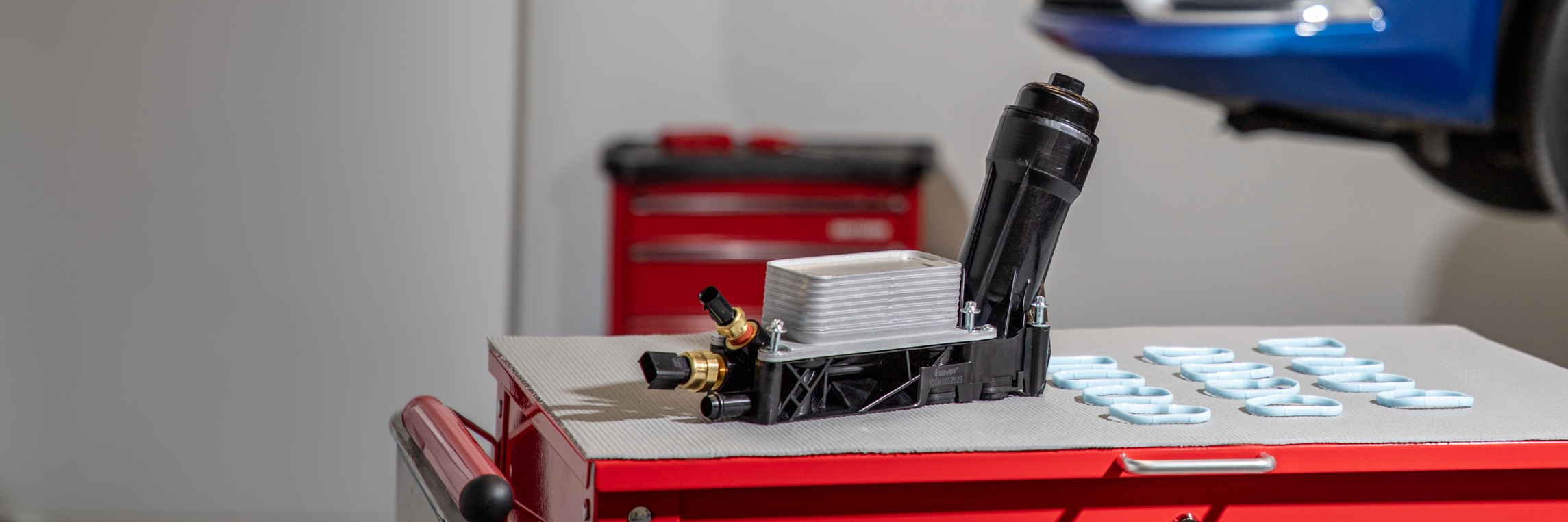
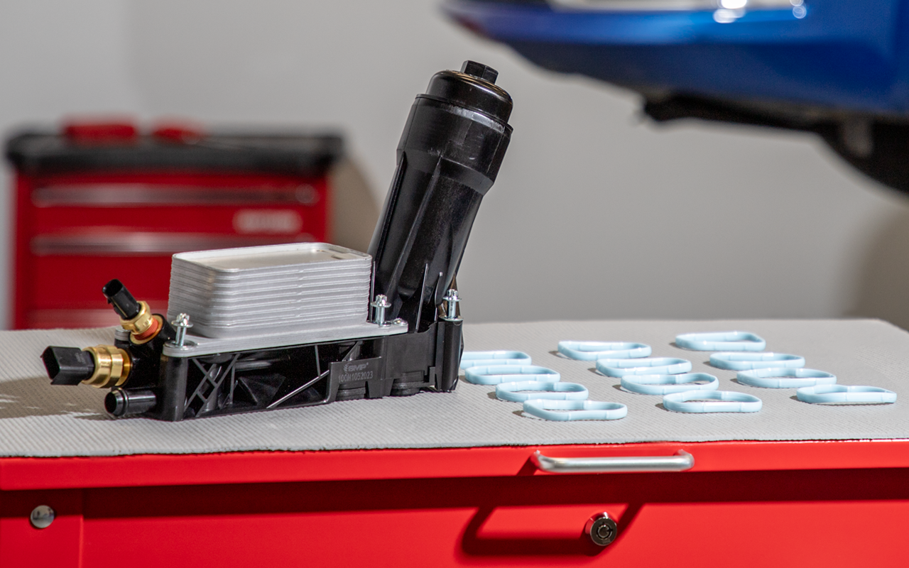
NAPA® Echlin® Oil Filter Housing Kits feature multiple design improvements over the OE to prevent oil leaks at OE weak points.
Our housings are factory-assembled, match the OE design’s thermal characteristics, and include all-new components for a complete repair.
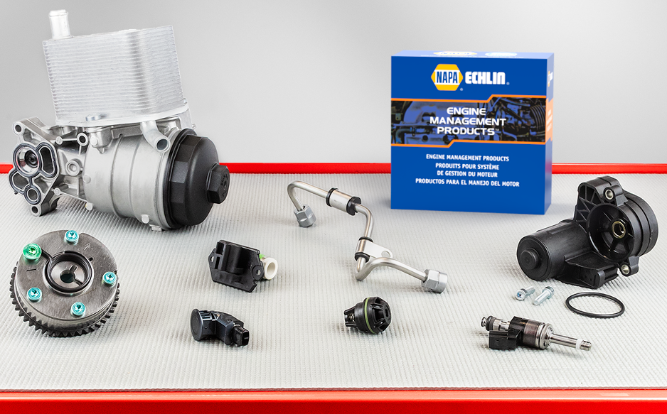
WHAT'S IN YOUR BOX?™
To prevent oil leaks from core plugs at the rear of the housing, NAPA® Echlin® installs an O-ring on each core plug before ultrasonically welding them into the housing. This creates a positive, long-lasting seal.
On OE units, oil leaks from the brass sensor inserts. To create an effective seal between the brass and the synthetic housing material, NAPA® Echlin® installs additional O-rings on our knurled brass inserts. Sensors are then installed and torqued to specification.
OE seals often become distorted or crushed, resulting in an oil leak around the base of the housing. To prevent leaks, NAPA® Echlin® installs distortion-resistant seals that are less prone to failure than the original.
Echlin® has announced the introduction of 123 new part numbers in its March new number announcement. This most recent release provides new coverage in 53 distinct product categories and 47 part numbers for 2023 and 2024 model-year vehicles.
Echlin® is pleased to share the expansion of its line of Oil Filter Housing Kits. Tech Expert® by Echlin® Oil Filter Housing Kits feature design improvements over the OE units, are application-specific, not universal, and come completely assembled from the factory for a drop-in solution.
Echlin® is pleased to announce the introduction of 118 new part numbers in its February new number announcement. This recent release provides new coverage in 57 distinct product categories and 55 part numbers for 2023 and 2024 model-year vehicles.
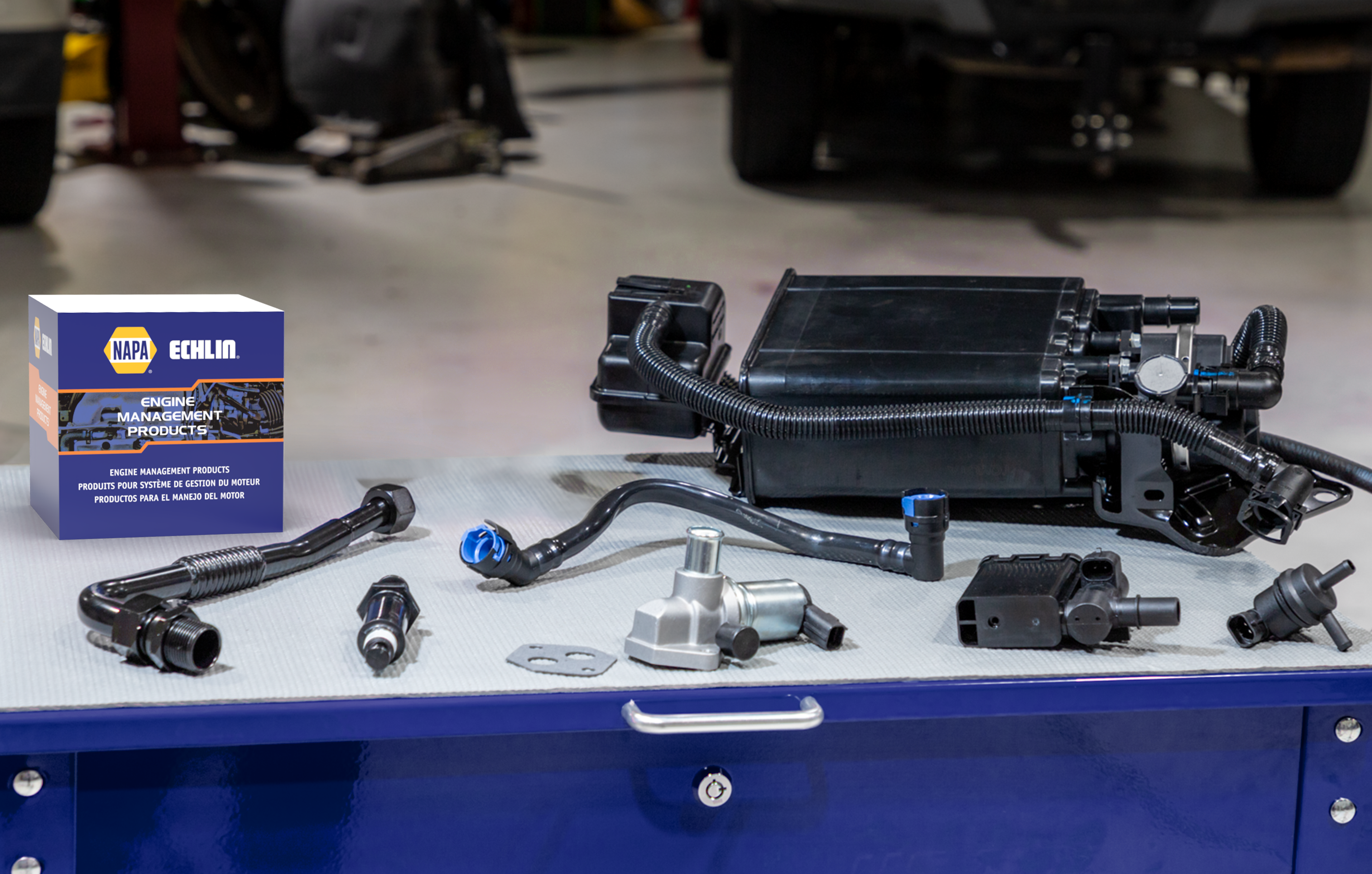
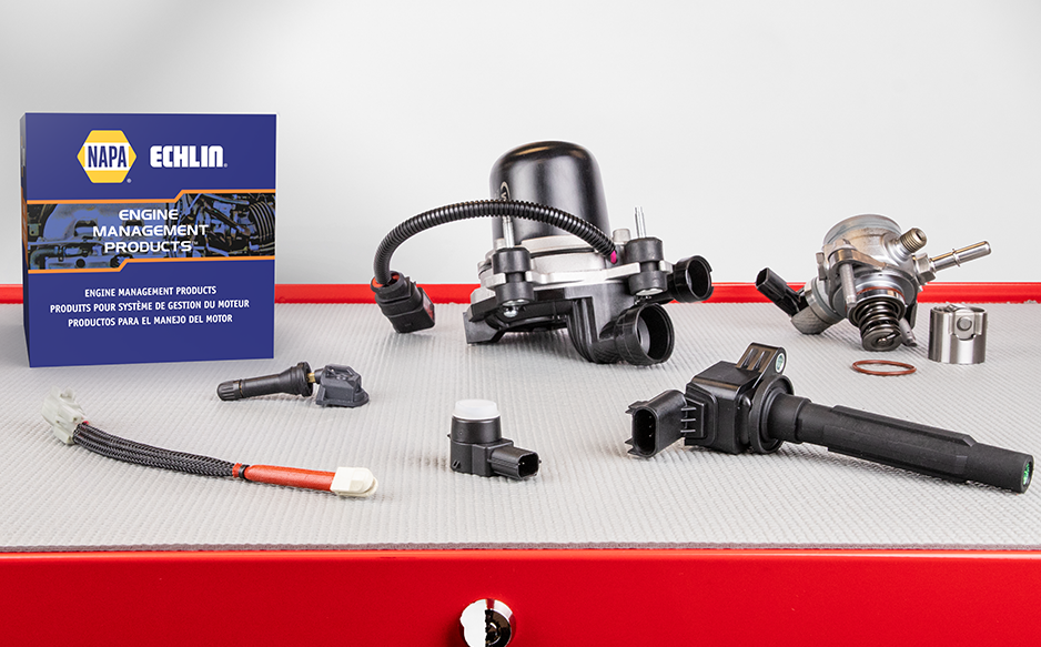
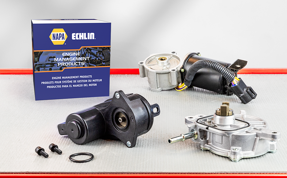
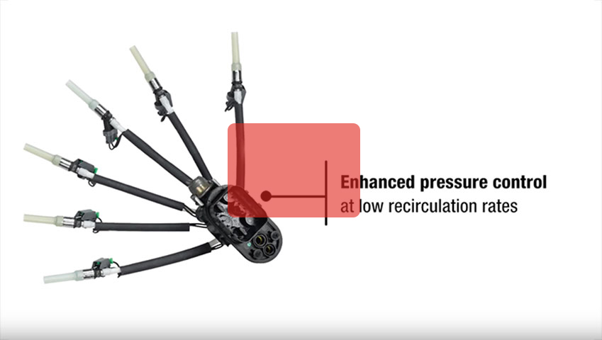
Echlin® is dedicated to expanding its comprehensive Emission Control program. NAPA® Echlin’s Emission Control program includes evaporative emission control (EVAP), exhaust gas recirculation (EGR), and positive crankcase ventilation emission control systems. With more than 3,500 part numbers, NAPA® Echlin® offers the most complete program in the industry, with everything needed for a complete repair.
Echlin® is pleased to announce the introduction of 208 new part numbers in its January new number announcement. This most recent release provides new coverage in 72 distinct product categories and 115 part numbers for 2022, 2023, and 2024 model-year vehicles.
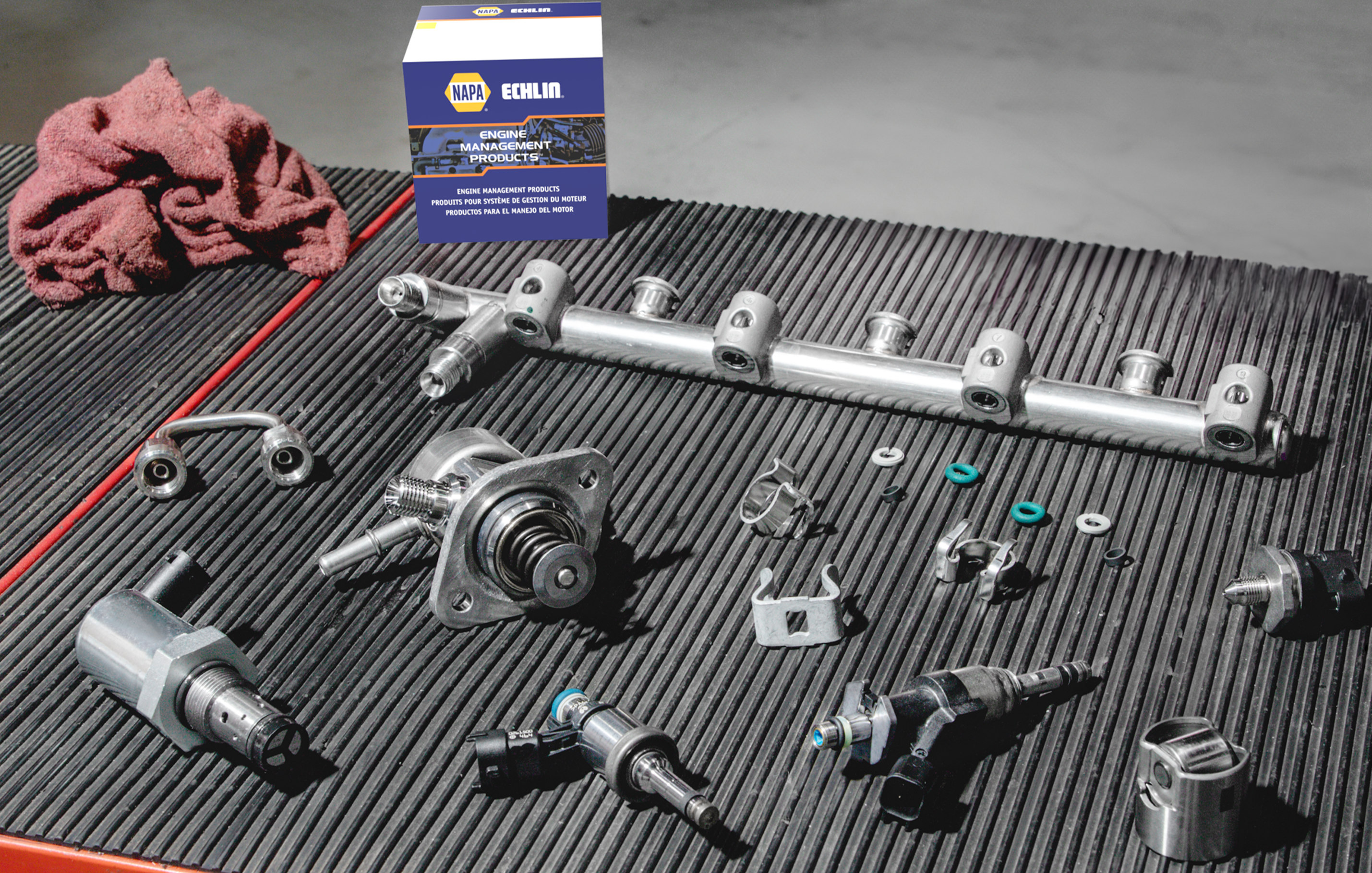
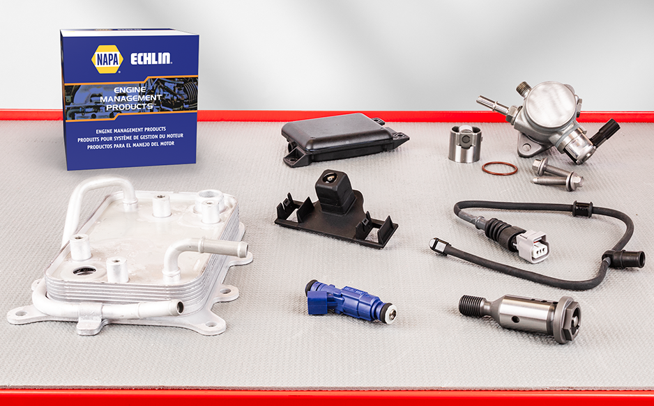
Echlin® continues to expand its aftermarket-leading Gasoline Fuel Injection program. With more than 2,100 part numbers, NAPA® Echlin® offers the most complete program in the industry, including everything needed for a complete repair.

Echlin® is pleased to announce that it released a total of 2,626 new part numbers in 2023. Closing out the year, Echlin® has released 227 new part numbers in its December new number announcement. This most recent release provides new coverage in 71 distinct product categories and 128 part numbers for 2022, 2023, and 2024 model-year vehicles.
Echlin® has released 276 new part numbers in its October new number announcement. This most recent release provides new coverage in 113 distinct product categories, and 118 part numbers for 2022, 2023, and 2024 model-year vehicles.

Echlin® continues to expand its line of Oil Filter Housing Kits. Since the program’s introduction, Echlin® has added coverage for many popular applications.
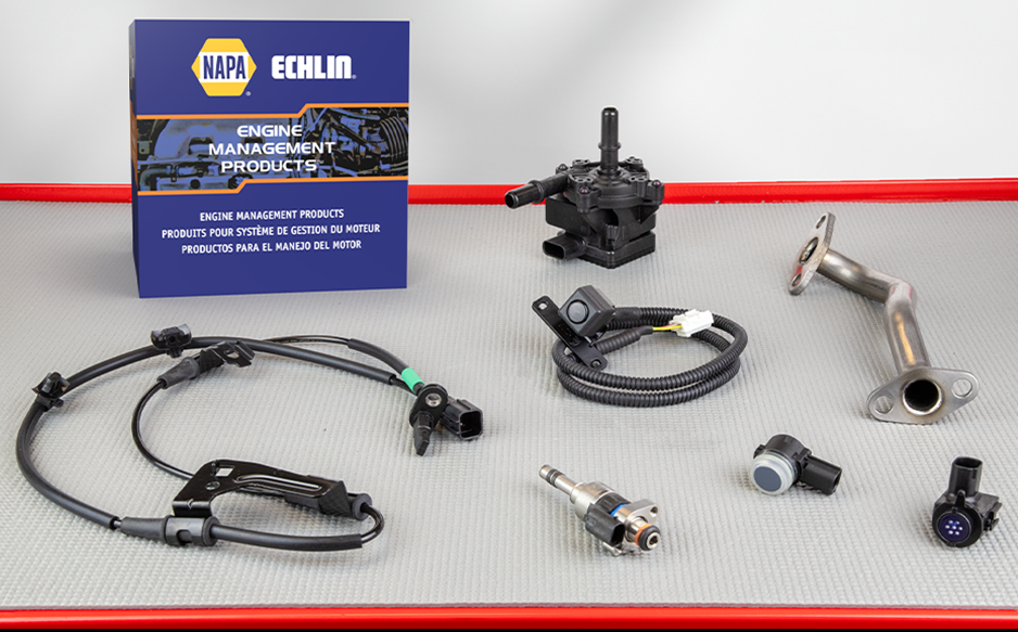
Echlin® is pleased to announce the expansion of additional categories covering import and domestic vehicles with ICE, hybrid, and electric powertrains. As the car parc evolves, Echlin® remains dedicated to introducing and expanding new product lines to provide technicians with the parts needed to do the job right, regardless of powertrain. When OE fails, technicians trust Echlin® to deliver precision components that keep a wide variety of systems operating as designed.
Echlin® has released 272 new part numbers in its September new number announcement. This most recent release provides new coverage in 89 distinct product categories, and 115 part numbers for 2022, 2023 and 2024 model-year vehicles.
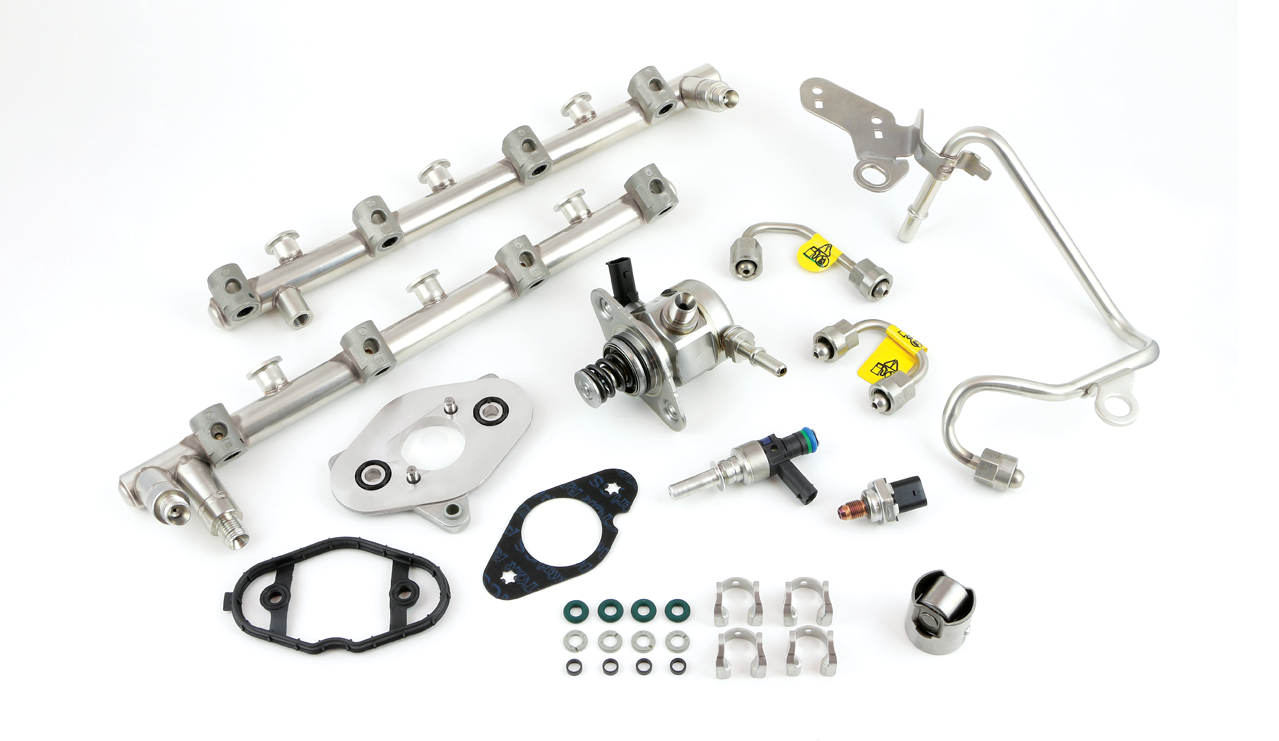
NAPA® Echlin® continues to expand its aftermarket-leading Gasoline Direct Injection (GDI) program. GDI technology has been an integral part of helping to improve fuel economy while reducing emissions, and can be found on more than half of the U.S. fleet.
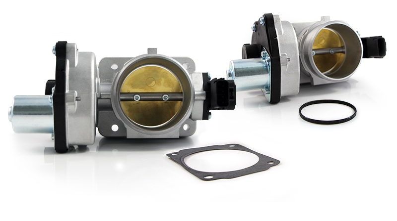
The most recent expansion to NAPA® Echlin’s Tech Expert® ETB offering features applications for popular import nameplates including Toyota, Nissan, Mazda, Hyundai, and Kia. Tech Expert® ETB line-up now includes more than 200 part numbers, and covers 190 million vehicles. Providing industry-leading, late-model coverage for domestic and import vehicles, Tech Expert® offers ETBs for 2021 and 2022 model years.
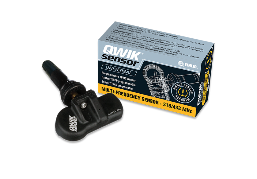
The New Multi-Frequency TPMS Sensor combines 314.9, 315, and 433/434 MHz applications into one single SKU, eliminating a duplication of customer inventory. The Single Sensor program is an addition to NAPA Echlin’s QWIK-SENSOR® Universal Programmable TPMS Sensors and OE-Match TPMS Sensors and provides coverage for more than 200 million vehicles-in-operation (VIO) in North America.
Check out how our sensors protect against over-voltage, under-voltage, reverse-voltage, and short circuits, and maintain accuracy during heavy-duty shock, vibration, and maximum temperature conditions.

Eric Sills, President and CEO of Standard Motor Products and incoming Board Chairman of AASA, spoke before the U.S. House of Representatives Committee on Energy & Commerce Subcommittee on Consumer Protection & Commerce. Sills was one of only four to testify on supply chain resilience and American competitiveness.
With a long history of design innovation, NAPA® Echlin’s product expertise and manufacturing capabilities are vital assets in making Belden® EDGE the most trusted name in spark plug wires.
Every time you take a NAPA® Echlin® part out of the box, you know you are holding in your hands the very best. Quality, durability, reliability, extensive testing…that’s what’s behind NAPA® Echlin® parts.

Auto manufacturers receive as much as 25GB of data per hour from your vehicle and get to decide where that data goes. Access to vehicle data is mission critical for us. That’s why we are working with the Auto Care Association and Automotive Aftermarket Suppliers Association (AASA) to raise consumer awareness of this issue and support industry advocacy efforts. Help us protect our industry and ensure consumer choice.
It’s Your Car. Your Data. And it should be Your Choice.
GM’s Vortec engines come with a Sequential Port Injection System (SCPI). NAPA Echlin’s Multi-Port Fuel Injection (MFI) system has several advantages over the original Sequential Central Port Injection (SCPI) system, including port fuel delivery and high reliability, better hot starts and reduced vapor emissions, and faster prime on hot restarts.

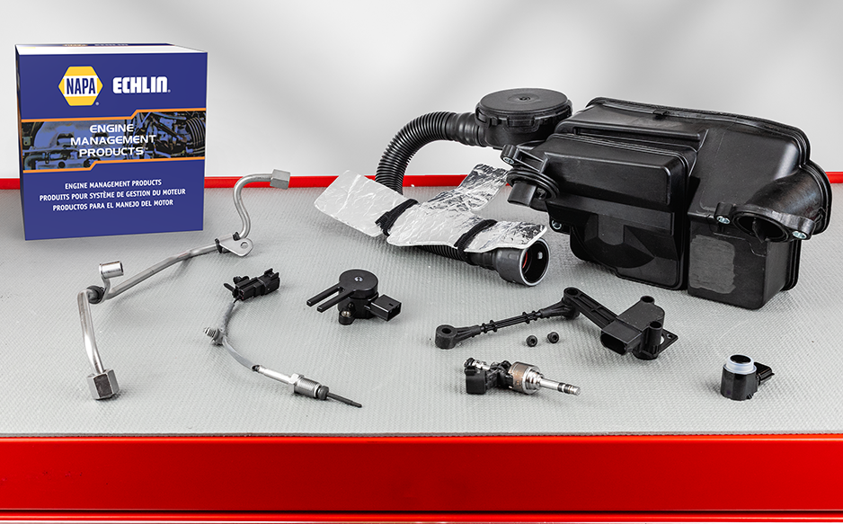
To account for the burgeoning diesel market, we have fully invested in diesel. Today, NAPA® Echlin® Diesel offers thousands of diesel parts across hundreds of unique diesel categories for popular applications including medium-duty trucks.
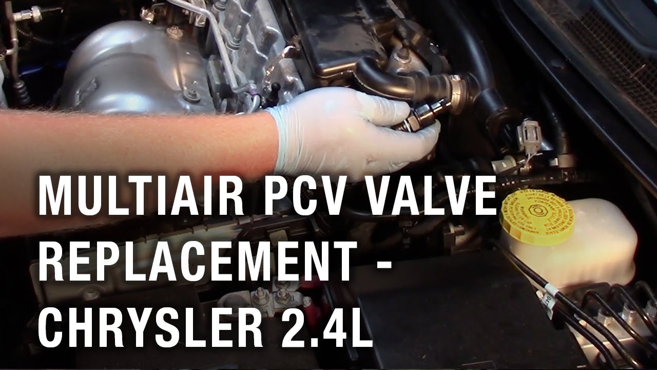
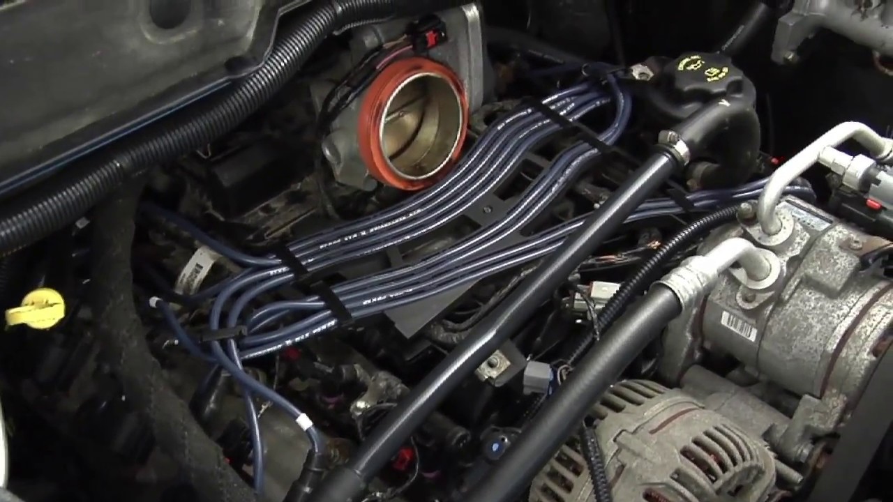
Our latest installation video shares helpful tips on replacing the Multiair PCV Valve on a Chrysler vehicle with a 2.4L engine. You can always count on NAPA Echlin to help you solve your automotive problems.
Do you have an idea for a part that we should offer? We want to hear from you directly.